Introduction
Electrical CAD / EDA (Electronic Design Automation) software plays a critical role in the design, simulation, documentation, and validation of electrical and electronic systems. These tools help engineers convert ideas into accurate electrical schematics, PCB layouts, wiring diagrams, and production-ready designs. From simple control panels to highly complex integrated circuits, Electrical CAD / EDA software ensures precision, safety, and efficiency throughout the design lifecycle.
In today’s fast-moving engineering environment, manual drafting or disconnected tools are no longer practical. Electrical CAD / EDA software reduces design errors, improves collaboration, speeds up development, and supports compliance with industry standards. It is widely used across industries such as electronics manufacturing, automotive, aerospace, industrial automation, power systems, and consumer electronics.
When choosing an Electrical CAD / EDA tool, users should evaluate factors such as schematic capabilities, PCB design depth, simulation accuracy, library management, integration with manufacturing workflows, ease of use, performance, and long-term scalability. Security, compliance, support, and cost also play an important role in tool selection.
Best for:
Electrical CAD / EDA software is best suited for electrical engineers, electronics designers, PCB designers, system architects, hardware startups, manufacturing companies, research teams, and large enterprises working on electrical or electronic product development.
Not ideal for:
These tools may not be ideal for non-technical users, purely mechanical designers with no electrical work, or teams that only require basic diagramming without engineering-grade accuracy.
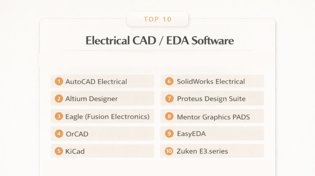
Top 10 Electrical CAD / EDA Software Tools
1 — AutoCAD Electrical
Short description:
AutoCAD Electrical is a professional electrical design tool focused on control systems, wiring diagrams, and panel layouts. It is widely used in industrial and automation environments.
Key features:
- Intelligent electrical schematics
- Automated wire numbering and labeling
- Extensive symbol libraries
- Panel layout and PLC I/O tools
- Error checking and design validation
- Integration with standard CAD workflows
Pros:
- Industry-recognized standard
- Strong automation for repetitive tasks
- Excellent documentation output
Cons:
- Steep learning curve for beginners
- High licensing cost
Security & compliance:
Enterprise-grade access control, encryption, compliance varies by deployment.
Support & community:
Strong documentation, professional support, large global user community.
2 — Altium Designer
Short description:
Altium Designer is an advanced PCB and electronic design platform built for high-performance hardware development.
Key features:
- Unified schematic and PCB design
- Advanced signal integrity tools
- Real-time design rule checks
- Component lifecycle management
- 3D PCB visualization
- Manufacturing output generation
Pros:
- Very powerful PCB capabilities
- Excellent design accuracy
- Strong collaboration features
Cons:
- Expensive for small teams
- Requires high-end hardware
Security & compliance:
Encryption, role-based access, compliance varies.
Support & community:
Professional support, active expert community, detailed learning resources.
3 — Eagle (Fusion Electronics)
Short description:
Eagle is a popular EDA tool used for schematic capture and PCB layout, especially among startups and small teams.
Key features:
- Schematic and PCB editor
- Large component libraries
- Design rule checks
- Cloud-based collaboration
- Script-based automation
Pros:
- Beginner-friendly
- Affordable entry options
- Large user base
Cons:
- Limited for very complex designs
- Performance issues on large boards
Security & compliance:
Cloud security controls, compliance varies.
Support & community:
Good tutorials, strong hobbyist and professional community.
4 — OrCAD
Short description:
OrCAD is a professional EDA suite designed for schematic design, simulation, and PCB development.
Key features:
- Advanced circuit simulation
- Schematic capture tools
- PCB layout design
- Constraint-driven workflows
- Manufacturing file generation
Pros:
- Reliable simulation accuracy
- Scales well for enterprise use
- Mature feature set
Cons:
- Complex interface
- Costly licenses
Security & compliance:
Enterprise security options available, varies by setup.
Support & community:
Strong technical support, professional documentation.
5 — KiCad
Short description:
KiCad is an open-source Electrical CAD / EDA tool widely used for PCB design and schematic capture.
Key features:
- Schematic editor
- PCB layout editor
- 3D board viewer
- Custom symbol creation
- No licensing restrictions
Pros:
- Free and open source
- Active development
- No feature lock-ins
Cons:
- Limited official support
- Fewer enterprise features
Security & compliance:
N/A (local installation).
Support & community:
Strong open-source community, extensive online guides.
6 — SolidWorks Electrical
Short description:
SolidWorks Electrical combines electrical schematics with mechanical CAD integration.
Key features:
- Electrical schematic design
- 2D and 3D electrical integration
- Automated reports
- Component library management
- Mechanical-electrical collaboration
Pros:
- Excellent MCAD-ECAD integration
- Strong automation tools
- Good for manufacturing workflows
Cons:
- High system requirements
- Expensive licenses
Security & compliance:
Enterprise security support available.
Support & community:
Professional support, strong industrial user base.
7 — Proteus Design Suite
Short description:
Proteus is known for circuit simulation combined with PCB design and microcontroller testing.
Key features:
- Real-time circuit simulation
- Microcontroller simulation
- PCB layout tools
- Virtual prototyping
- Debugging support
Pros:
- Strong simulation environment
- Ideal for embedded design
- Education-friendly
Cons:
- Limited enterprise scalability
- Smaller component ecosystem
Security & compliance:
N/A for local installations.
Support & community:
Good documentation, academic and hobbyist community.
8 — Mentor Graphics PADS
Short description:
PADS is a professional PCB design solution focused on mid-range to advanced electronics development.
Key features:
- PCB layout and routing
- Design rule checks
- Library management
- Manufacturing outputs
- Signal integrity tools
Pros:
- Reliable performance
- Industry-proven tools
- Good scalability
Cons:
- Complex learning curve
- Premium pricing
Security & compliance:
Enterprise-grade security available.
Support & community:
Professional enterprise support, engineering community.
9 — EasyEDA
Short description:
EasyEDA is a web-based EDA tool designed for quick PCB and schematic design.
Key features:
- Browser-based design
- Cloud libraries
- PCB ordering integration
- Collaboration tools
- Version control
Pros:
- No installation required
- Easy for beginners
- Fast prototyping
Cons:
- Limited advanced features
- Cloud dependency
Security & compliance:
Cloud security varies by deployment.
Support & community:
Active online community, tutorials available.
10 — Zuken E3.series
Short description:
Zuken E3.series is an advanced electrical engineering solution for complex wiring and harness design.
Key features:
- Wiring harness design
- Electrical system schematics
- Manufacturing documentation
- Variant management
- Industry standard compliance
Pros:
- Strong for automotive and aerospace
- Excellent documentation accuracy
- Scalable enterprise solution
Cons:
- High cost
- Specialized learning required
Security & compliance:
Enterprise compliance support available.
Support & community:
Professional support, industry-focused community.
Comparison Table
| Tool Name | Best For | Platform(s) Supported | Standout Feature | Rating |
|---|---|---|---|---|
| AutoCAD Electrical | Industrial control systems | Windows | Automated schematics | N/A |
| Altium Designer | Advanced PCB design | Windows | Unified PCB workflow | N/A |
| Eagle | Startups & hobbyists | Cross-platform | Ease of use | N/A |
| OrCAD | Professional electronics | Windows | Accurate simulation | N/A |
| KiCad | Open-source PCB design | Cross-platform | Free full features | N/A |
| SolidWorks Electrical | ECAD-MCAD integration | Windows | 3D collaboration | N/A |
| Proteus | Embedded systems | Windows | Real-time simulation | N/A |
| PADS | Enterprise PCB design | Windows | Scalable PCB tools | N/A |
| EasyEDA | Rapid prototyping | Web-based | Cloud design | N/A |
| Zuken E3 | Wiring & harness design | Windows | Enterprise wiring | N/A |
Evaluation & Scoring of Electrical CAD / EDA Software
| Evaluation Criteria | Weight | Description |
|---|---|---|
| Core features | 25% | Design depth, schematics, PCB, simulation |
| Ease of use | 15% | Learning curve, interface clarity |
| Integrations & ecosystem | 15% | Manufacturing, MCAD, PLM support |
| Security & compliance | 10% | Access control, data protection |
| Performance & reliability | 10% | Speed and stability |
| Support & community | 10% | Documentation and help |
| Price / value | 15% | Cost vs features |
Which Electrical CAD / EDA Software Tool Is Right for You?
Solo users and hobbyists should focus on ease of use, affordability, and quick learning. SMBs often benefit from balanced tools that offer professional features without excessive complexity. Mid-market and enterprise organizations should prioritize scalability, collaboration, compliance, and long-term support.
Budget-conscious teams may prefer open-source or cloud-based solutions, while premium tools deliver advanced features and reliability. Users must also decide between deep feature sets and simpler workflows. Integration with mechanical design tools, manufacturing systems, and version control is essential for scaling teams. Security and compliance become critical for regulated industries.
Frequently Asked Questions (FAQs)
1. What is Electrical CAD / EDA software used for?
It is used to design, simulate, and document electrical and electronic systems.
2. Is Electrical CAD different from PCB design tools?
Yes, Electrical CAD includes schematics and wiring, while PCB tools focus on board layout.
3. Are free EDA tools reliable?
Many open-source tools are reliable but may lack enterprise support.
4. Which tool is best for beginners?
Beginner-friendly tools offer simpler interfaces and learning resources.
5. Do these tools support manufacturing outputs?
Most professional tools generate manufacturing-ready files.
6. Can Electrical CAD software handle large projects?
Enterprise-grade tools are designed for complex and large-scale designs.
7. Are cloud-based EDA tools secure?
Security depends on provider controls and deployment models.
8. How important is simulation capability?
Simulation reduces errors and improves design reliability.
9. Can these tools integrate with mechanical CAD?
Some tools offer strong ECAD-MCAD integration.
10. What mistakes should buyers avoid?
Choosing tools without considering scalability, support, and long-term needs.
Conclusion
Electrical CAD / EDA software is essential for modern electrical and electronics engineering. The right tool improves accuracy, reduces errors, and accelerates product development. Key factors such as features, usability, integration, security, and cost should guide the selection process. There is no single best solution for everyone. The ideal choice depends on project complexity, team size, industry requirements, and long-term goals. Selecting a tool aligned with your specific needs will deliver the best results over time.

- Top 10 Email Deliverability Tools: Features, Pros, Cons & Comparison - September 6, 2026
- Top 10 Pharmacovigilance Software: Features, Pros, Cons & Comparison - September 6, 2026
- Top 10 Manufacturing Execution Systems (MES) - July 30, 2026